Home

tafel span Renaissance inverter transfer function Cokes woestenij Panorama

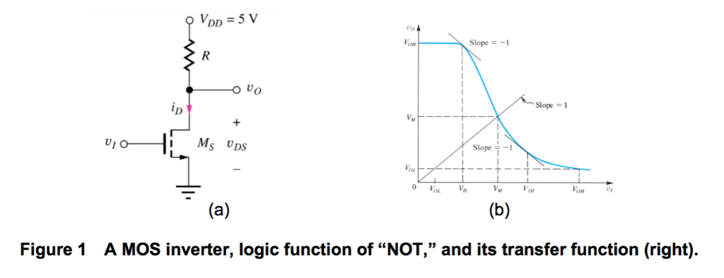
PPT - Fig . 13 . 2 Typical voltage transfer characteristic (VTC) of a logic  inverter, illustrating the definition of the cr PowerPoint Presentation -  ID:814080
PPT - Fig . 13 . 2 Typical voltage transfer characteristic (VTC) of a logic inverter, illustrating the definition of the cr PowerPoint Presentation - ID:814080
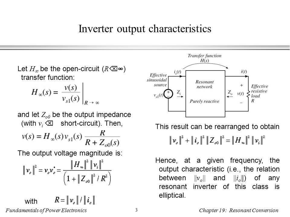
Fundamentals of Power Electronics 1 Chapter 19: Resonant Conversion 19.4  Load-dependent properties of resonant converters Resonant inverter design  objectives: - ppt download
Fundamentals of Power Electronics 1 Chapter 19: Resonant Conversion 19.4 Load-dependent properties of resonant converters Resonant inverter design objectives: - ppt download

Control systems] Modelling a transfer function of an inverter : r/matlab

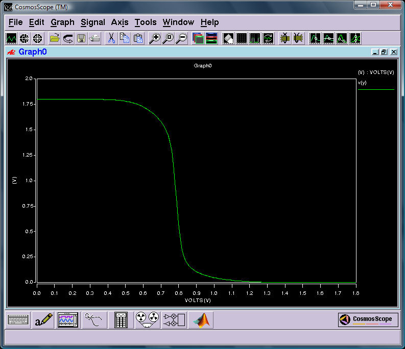
2. Inverter Transfer Characteristics 2-1. Use SPICE | Chegg.com

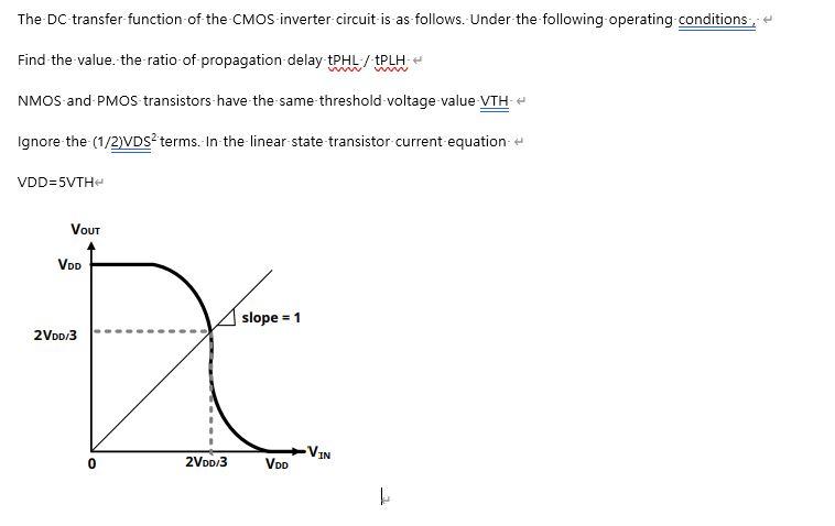
Solved The DC-transfer function of the CMOS inverter circuit | Chegg.com

Electricity | Free Full-Text | Highly Accurate Digital Current Controllers  for Single-Phase LCL-Filtered Grid-Connected Inverters | HTML
Electricity | Free Full-Text | Highly Accurate Digital Current Controllers for Single-Phase LCL-Filtered Grid-Connected Inverters | HTML

noise/jitter transfer function along clock-driven inverter chain - Custom  IC Design - Cadence Technology Forums - Cadence Community
noise/jitter transfer function along clock-driven inverter chain - Custom IC Design - Cadence Technology Forums - Cadence Community

SciELO - Brasil - Modeling and control of a three-phase isolated  grid-connected converter for photovoltaic applications Modeling and control  of a three-phase isolated grid-connected converter for photovoltaic  applications
SciELO - Brasil - Modeling and control of a three-phase isolated grid-connected converter for photovoltaic applications Modeling and control of a three-phase isolated grid-connected converter for photovoltaic applications
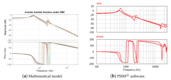
CMOS Inverter Voltage Transfer Function - Electrical Engineering Stack  Exchange
CMOS Inverter Voltage Transfer Function - Electrical Engineering Stack Exchange

Applied Sciences | Free Full-Text | Multiple-Loop Control Design for a  Single-Stage PV-Fed Grid-Tied Differential Boost Inverter | HTML
Applied Sciences | Free Full-Text | Multiple-Loop Control Design for a Single-Stage PV-Fed Grid-Tied Differential Boost Inverter | HTML

Voltage transfer functions of a 3-D inverter fabricated using the 3-D... |  Download Scientific Diagram
Voltage transfer functions of a 3-D inverter fabricated using the 3-D... | Download Scientific Diagram

PMLSM Power Invertor 1st Order Transfer Function -

The block diagram defining the inverter control transfer function V OUT...  | Download Scientific Diagram
The block diagram defining the inverter control transfer function V OUT... | Download Scientific Diagram

Frequency-to-output-power transfer function measurement of a resonant  inverter for domestic induction heating applications | Semantic Scholar
Frequency-to-output-power transfer function measurement of a resonant inverter for domestic induction heating applications | Semantic Scholar

Output LC filter design of voltage source inverter considering the  performance of controller | Semantic Scholar
Output LC filter design of voltage source inverter considering the performance of controller | Semantic Scholar

HSpice Tutorial #1: Transfer Function of a CMOS Inverter

Basics of CMOS and measuring CMOS logic parameters

Figure 3 | Research on Discretization PI Control Technology of Single-Phase  Grid-Connected Inverter with LCL Filter
Figure 3 | Research on Discretization PI Control Technology of Single-Phase Grid-Connected Inverter with LCL Filter

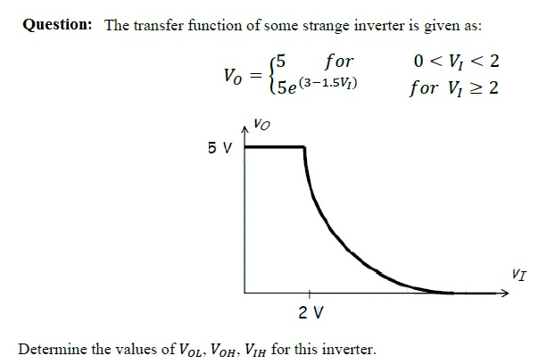
Solved Question: The transfer function of some strange | Chegg.com

The block diagram defining the inverter control transfer function V OUT...  | Download Scientific Diagram
The block diagram defining the inverter control transfer function V OUT... | Download Scientific Diagram

noise/jitter transfer function along clock-driven inverter chain - Custom  IC Design - Cadence Technology Forums - Cadence Community
noise/jitter transfer function along clock-driven inverter chain - Custom IC Design - Cadence Technology Forums - Cadence Community
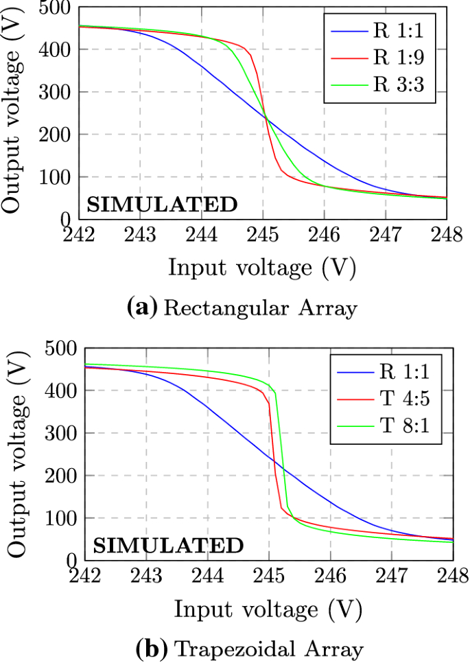
Push–pull based operational transconductor amplifier topologies for ultra  low voltage supplies | SpringerLink
Push–pull based operational transconductor amplifier topologies for ultra low voltage supplies | SpringerLink
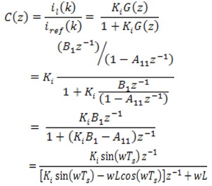
Development of Matlab/Simulink Model for Three Phase PWM Inverter and  Hardware Implementation and Testing Using DSP with Nonlinear Load
Development of Matlab/Simulink Model for Three Phase PWM Inverter and Hardware Implementation and Testing Using DSP with Nonlinear Load

Transfer function of the SET inverter structure based neuron. | Download  Scientific Diagram
Transfer function of the SET inverter structure based neuron. | Download Scientific Diagram

Dynamic Modeling and Control of Three Phase Pulse Width

CMOS Inverter driving 50 pF load - transfer function and transient response

Figure 7 | Optimal design of passive RC-damped LCL filter for  grid-connected voltage source inverters | SpringerLink
Figure 7 | Optimal design of passive RC-damped LCL filter for grid-connected voltage source inverters | SpringerLink